凡例の置換表記凡例の置換表記
Originにおけるグラフの凡例
Originのグラフには4つの基本的な凡例があります。
- データプロットの凡例: ほとんどの2Dや3Dグラフのデフォルトの凡例はプロットシンボルに列のメタデータ(例:列のロングネーム)から派生したテキストを結合したものです。
- カテゴリ値の凡例: 凡例の項目はプロットのシンボル--ワークシートデータの列にあるそれぞれのカテゴリの1つ--にカテゴリの名前を表すテキストを結合したのもです。カテゴリの凡例は複数のカテゴリ変数(カテゴリデータを表す複数の列)を表すことができ、カテゴリ変数ごとにシンボルのバリエーションが一覧表示されます。
- ボックスチャートコンポーネントの凡例: 凡例の項目は通常、プロットシンボルに列のメタデータかカテゴリラベルを結合したものに加えて、表示された統計のシンボリックリストとも組み合わせます。
- 1ポイントずつの凡例: プロットシンボルに数字(数字はインデックスかデータの値を表します)を組み合わせた凡例です。全てのデータポイントが凡例の項目に生成されるので、この凡例タイプは特定のプロットタイプ(例:トリリニアダイアグラム)や小さいデータセットに最も適しています。
次の情報は、さまざまな凡例の背後にある変数の構文を理解し、必要に応じて凡例をオブジェクトのコンテンツを変更するのに役立ちます。
データプロットの凡例(ほとんどの2D・3Dグラフ)
ほとんどの2D・3Dグラフでは、凡例は次の置換構文に従って作成されます。
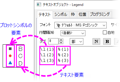
プロットシンボルのコンポーネント: \L([LayerIndex.]PlotIndex[,PointIndex[,option]])
テキストコンポーネント: %(LayerIndex.PlotIndex[Axis, @option])
これは凡例オブジェクトを右クリックし、プロパティを選択したときに表示されます。:
2つの注意事項:
- シンボルコンポーネントは\L()によって囲まれ、テキストコンポーネントは%()によって囲まれます。
- 構文モデル内の角括弧はオプションの引数を示すだけなので、角括弧を入力する必要はありません。
プロットシンボルのコンポーネント
この表記は特定のデータプロットのシンボルを表示することにより、凡例のデータプロットシンボルを構成することに使用されます。LayerIndexはオプションですが、省略した場合にはアクティブレイヤが想定されます。加えて、オプションのPointIndexは特別なデータポイントに割り当てられたシンボルを表示するのに使用されます。
基本構文:
\L([LayerIndex.]PlotIndex[,PointIndex[,Option]])
ここでは、
- LayerIndex(オプション): 特定のデータプロットのレイヤで、1からのインデックスになっています。アクティブレイヤを指す場合にはこのオプションは省略でき、\L(PlotIndex)のようになります。
- PlotIndex: データメニューの下部もしくはレイヤの内容のデータリスト内でのデータプロットの位置(1からのインデックス)Note: このリストはアクティブなグラフレイヤのすべてのプロット用です。
- PointIndex(オプション): データプロットの1点がカスタマイズされている場合、このオプションはその1点シンボルを表示するために使用されます。
- Option: 通常、プロットシンボルは、指定されたレイヤの指定されたデータプロットの最初の点の表現(散布図シンボルなど)、またはデータプロットの表現(折れ線グラフの線など)で生成されます。または、PointIndexが指定されている場合は、指定された点の表現になります。ただし、次のサンプルで示すように、凡例データプロットシンボルをカスタマイズして、データプロットとは独立して表示することができます。必要に応じて、グラフウィンドウのデータプロット(シンボル、線+シンボル、線種)から完全に独立したプロットシンボルを生成できます。詳細はこのセクションを参照してください。
シンボルの部分的なプロパティの凡例
| 凡例の項目
|
説明
|
例
|
| \l(1) %(1)
|
もとの線+シンボルプロット
|

|
| \l(1, style:s) %(1)
|
線+シンボルプロットのうちシンボルのみを表示
|

|
| \l(1, style:l) %(1)
|
線+シンボルプロットのうち線のみを表示
|

|
| \l(1, style:sls)
|
線+シンボルプロットをシンボル線シンボルの順で表示
|

|
スケーリングされたシンボルの凡例
| 凡例の項目
|
説明
|
例
|
| \l(1) %(1)
|
もとの線+シンボルプロット
|

|
| \l(1, size:5) %(1)
|
シンボルのサイズを5にして表示
|

|
| \l(1, size:p150) %(1)
|
シンボルのサイズを元のシンボルサイズの150%にして表示
|

|
| \l(1, LineWidth:3) %(1)
|
線分の幅を3にして表示
|

|
| \l(1, LineWidth:p1000) %(1)
|
線分をもとの線幅の1000%にして表示
|

|
| \l(1, Length:p50) %(1)
|
線分をもとの長さの50%にして表示
|

|
| \l(1) %(1)
|
もとの縦棒プロット
|

|
| \l(1, PatternHeight:p50) %(1)
|
棒をもとの高さの50%にして表示
|

|
| \l(1, PatternWidth:p50) %(1)
|
棒をもとの幅の50%にして表示
|

|
棒グラフ要素の凡例
| 凡例の項目
|
説明
|
例
|
| \l(1) Bar
|
もとの棒グラフプロット(1つ目のレイヤの1番目のプロット)
|

|
| \l(1, style:C) Fill Color
|
塗りつぶしの色の棒グラフプロットを表示
|

|
| \l(1, 1, 2) Fill Color
|
ブロックを1つ目のレイヤの1番目棒グラフプロットの塗りつぶしの色にして表示
|

|
| \l(1, style:P) Pattern
|
棒グラフプロットのパターンを表示
|

|
| \l(1, style:P#81F7F3) Custom Fill Color
|
指定した色で塗りつぶして凡例を表示
|

|
| \l(1, 1, 1) Border Color
|
ブロックを1つ目のレイヤの1番目棒グラフプロットの縁の色にして表示
|

|
| \l(1, 1, 3) Pattern Color
|
ブロックを1つ目のレイヤの1番目棒グラフプロットのパターンの色にして表示
|

|
 | レイヤ内のどのプロットにも関連付いていないシンボル、線+シンボル、および折れ線タイプのプロットシンボルを凡例に追加することができます。詳細は、プロットで使用されていないシンボルの追加を参照してください。
|
テキストコンポーネント
凡例テキストは文字テキストを使って(手動で)作成できますが、より一般的で効率のよい方法で置換表記というものがあります。これはデータプロットに紐づいたメタデータをLabTalk変数を使って表示する方法です。これらのメタデータには「@」オプションを指定することでアクセスでき、グラフの作図の詳細ダイアログボックスの凡例/タイトルタブで指定されたデフォルトの凡例構成を上書きするために使用できます。前述のように、角括弧はオプションの引数を示し、凡例テキストを作成するときには入力しません。
基本構文
%([LayerIndex.]PlotIndex[Axis[, @option]])
ここでは、
- LayerIndex(オプション): 特定のデータプロットのレイヤで、1からのインデックスになっています。アクティブレイヤを指す場合にはこのオプションは省略でき、\L(PlotIndex)のようになります。
- PlotIndex: データメニューの下部もしくはレイヤの内容のデータリスト内でのデータプロットの位置(1からのインデックス)Note: このリストはアクティブなグラフレイヤのすべてのプロット用です。
- Axis: 特定のレイヤやプロットで、X、YまたはZはどのソースデータ列が参照されているかを表します。指定がない(デフォルトの)とき、2DグラフではY、3DグラフではZとみなされます。
- @Option:: このオプションはグラフテンプレートに保存されたデフォルトの凡例の自動更新モードを上書きするために使用されます。グラフの凡例に関連した@optionのリストについては、このページの凡例テキストの編集のセクションをご覧ください。
サンプル
| 凡例の項目
|
説明
|
|
\l(1) %(1)
\l(2) %(2)
|
2つの行はアクティブレイヤのデータプロットの凡例です。最初の行は1つ目のプロットのもので、次の行は2つ目のプロットのものです。
グラフの作図の詳細ダイアログにある凡例/タイトルタブで指定された一般的なデフォルト設定では、凡例のラベルはソースデータワークシートでコメントを探し、コメントがない場合にはロングネームを使用します。ロングネームもない場合にはショートネームを使用します。
|
|
\l(1.1) %(1.1)
\l(2.1) %(2.1)
|
最初の行は1つ目のレイヤの1番目のプロットの凡例で、次の行は2つ目のレイヤの1番目のプロットの凡例です。
|
|
\l(1) %(1, @LD1)
\l(1) %(1Y, @LD1)
\l(1) %(1, @LD"UserP Name")
|
凡例のシンボルはアクティブレイヤの最初のプロットのもので、凡例ラベルはソースデータワークシートのY列にある最初のユーザパラメータを使用します。Yはオプションなので2Dでは同一のものを表します。ユーザパラメータの行番号または名前(名前にスペースがある場合には、ダブルクォーテーションで囲みます)でパラメータを参照できます。
|
|
\l(1) %(1X, @L)
|
凡例のシンボルはアクティブレイヤの最初のプロットのもので、凡例ラベルはソースデータワークシートのX列のロングネームを使用します。
|
|
\l(2.3, 5) %(2.3X, @LU) Lowest Value
|
凡例のシンボルは2つ目のレイヤの3番目のプロットの5番目の点のもので、凡例ラベルはソースデータワークシートのX列の単位を使用し、さらに次のユーザの指定テキストを付け加えます:Lowest Value
|
|
\l(1, 3, 2) %(1)
|
凡例シンボルはアクティブレイヤの3番目のシンボルで、使用されるプロット要素は内部の色です。
|
Notes:
- オブジェクトプロパティの プログラミングタブにある(%,$)にリンク,置換レベルを1に設定すると任意のテキストオブジェクトにこの構文を含めることができ、凡例のように機能します。
- 任意の凡例オブジェクトのアクティブなレイヤ はオブジェクトが接続されたレイヤです。
- 任意の1つのレイヤにはLegendという名前のオブジェクトは1つのみが存在できます。
カテゴリ値の凡例
Originでは、カテゴリデータセット内のそれぞれの「値」はプロットや分析操作をするために1から始まるインデックス値でマッピングされます。このインデックス値はプロット順などを制御するため、 使い方に合わせてカテゴリ値を変更することができます。
標準のデータプロットの凡例と同様に、Originは特別な構文を使用してプロットシンボルとテキストがカテゴリ値凡例に表示される方法を制御します。この特殊な凡例タイプに対応するには、グラフが特定の要件を満たしている必要があります。詳細はプロット要件をご覧ください。
プロットシンボルコンポーネント: \L(PlotIndex[.DataPoint], mCategoryIndex, PlotElement)
テキストコンポーネント: %(PlotIndex, mCategoryIndex, PlotElement)
注意事項:
- 構文は標準の凡例に似ていますが、プロットシンボルとテキストコンポーネントの両方の2番目の引数にmの文字 が含まれています。
プロットシンボルとテキストコンポーネント
基本構文
\L(PlotIndex[.DataPoint], mCategoryIndex, PlotElement) %(PlotIndex, mCategoryIndex, PlotElement)
ここでは、
- PlotIndex: プロット順(作図の詳細もしくは データリストで確認できます)を示す値です。
- DataPoint: データポイントの行インデックスの値です。
- CategoryIndex: 特定のカテゴリ値のインデックス番号です。(列のソート の状態で決定されます)
- PlotElement: データセット内のカテゴリにインデックス付けされているプロット要素を表す整数パラメータは1から14の値をとり、1=縁の色, 2=塗りつぶしの色, 3=パターンの色, 4=シンボルの形, 5=シンボルの内部, 6=シンボルのサイズ, 7=線のスタイル, 8=塗りつぶしパターン, 9=ボックスチャートの接続線, 10=ベクトルの色, 11=ベクトルのスタイル, 12=線のスタイル, 13=線の幅, 14=バイオリンプロットの塗りつぶしの色 となっています。パターンの色(パターン タブで定義されているもの)を除いて、すべてのプロット要素はプロットの シンボル タブで制御されます。すべての値が特定のプロットスタイルに対して有効であるとは限りません。この場合、無効なエントリは、赤いボックス内の赤いxまたは中空の黒い四角で示されます。

各プロット要素は、プロット要素と列メタデータから派生したデータセット識別子を組み合わせた凡例の項目を生成します。上記の例では、PlotElement =Symbol Color (縁の色) の場合、識別子は「Gender」です。この識別子は下記のリストから選択した「@option」によって決定されます。「Gender」というテキストを生成する残りの部分はPlotElementのインデックス作成に使用されるブックや列を識別するものであり、変更することを意図したものではありません。
サンプル:
| 凡例の項目
|
説明
|
Edge Color %(Book, @option, ColumnIndex)
\l(1, m1, 1) %(1, m1, 1)
\l(1, m2, 1) %(1, m2, 1)
\l(1, m3, 1) %(1, m3, 1)
|
シンボルの縁の色はカテゴリデータセットによって制御されます。
|
Color %(Book, @option, ColumnIndex)
\l(1,m1,1) %(1,m1,1)
\l(1,m2,1) %(1,m2,1)
|
シンボルの色はカテゴリデータセットによって制御されます。
|
Fill Color %(Book, @option, ColumnIndex)
\l(1, m1, 2) %(1, m1, 2)
\l(1, m2, 2) %(1, m2, 2)
\l(1, m3, 2) %(1, m3, 2)
|
シンボルの塗りつぶしの色はカテゴリデータセットによって制御されます。
|
Fill Pattern %(Book, @option, ColumnIndex)
\l(1,m1,8 1 2 3) %(1,m1,8)
\l(1,m2,8 1 2 3) %(1,m2,8)
\l(1,m3,8 1 2 3) %(1,m3,8)
|
塗りつぶしのパターンはカテゴリデータセットによって制御されます。
|
Pattern Color %(Book, @option, ColumnIndex)
\l(1,m1,3) %(1,m1,3)
\l(1,m2,3) %(1,m2,3)
|
パターンの色はカテゴリデータセットによって制御されます。
|
Shape %(Book, @option, ColumnIndex)
\l(1, m1, 4) %(1, m1, 4)
\l(1, m2, 4) %(1, m2, 4)
\l(1, m3, 4) %(1, m3, 4)
|
シンボルの形はカテゴリデータセットによって制御されます。(2Dグラフのみ)
|
Interior %(Book, @option, ColumnIndex)
\l(1, m1, 5) %(1, m1, 5)
\l(1, m2, 5) %(1, m2, 5)
\l(1, m3, 5) %(1, m3, 5)
\l(1, m4, 5) %(1, m4, 5)
|
シンボルの内部はカテゴリデータセットによって制御されます。(2Dのシンボルのみ)
|
Size %(Book, @option, ColumnIndex)
\l(1, m1, 6) %(1, m1, 6)
\l(1, m2, 6) %(1, m2, 6)
|
シンボルサイズはカテゴリデータセットによって制御されます。
|
ボックスチャートコンポーネントの凡例
ほかの凡例タイプと同様にボックスチャートコンポーネントの凡例もシンボルコンポーネントとテキストコンポーネントで構成されています。ただ、この構文はボックスチャートの凡例で固有のものです。
プロットシンボルのコンポーネント
\L(PlotIndex,ComponentChar)
テキストコンポーネント
%(PlotIndex, @V"Box_ComponentChar")
ComponentCharの値
- PlotIndex: データプロットの番号を定義する整数
- ComponentChar: ボックスチャートのコンポーネントを定義する1つ以上の文字テキスト置換では、文字の前にBox_が付き、ダブルクォーテーションで囲まれていることに注意してください。

| 文字
|
説明(置換テキスト)
|
例
|
| B
|
ボックスそのものこの文字はプロットシンボルコンポーネントにのみ使用されます。
|
\L(1,B) ----------
|
| R
|
ボックスの範囲(例: 25%~75%)この文字はテキストコンポーネントにのみ使用されます。
|
---------- %(1, @V"Box_R")
|
| W
|
ボックスのヒゲ(例 外れ値)
|
\L(1,W) %(1,@V"Box_W")
|
| MDL
|
ボックスの中央値線(中央値線)
|
\L(1,MDL) %(1,@V"Box_MDL")
|
| ML
|
ボックスの平均線(平均線)
|
\L(1,ML) %(1,@V"Box_ML")
|
| Max
|
ボックスの最大のパーセンタイルポイント(最大)
|
\L(1,Max) %(1,@V"Box_Max")
|
| P99
|
ボックスの99%パーセンタイルポイント(99%)
|
\L(1,P99) %(1,@V"Box_P99")
|
| M
|
ボックスのの平均パーセンタイルポイント(平均)
|
\L(1,M) %(1,@V"Box_M")
|
| P1
|
ボックスの1%パーセンタイルポイント(1%)
|
\L(1,P1) %(1,@V"Box_P1")
|
| Min
|
ボックスの最小パーセンタイルポイント(最小)
|
\L(1,Min) %(1,@V"Box_Min")
|
| D
|
ボックスのデータポイント(データ)
|
\L(1,D) %(1,@V"Box_D")
|
| O
|
ボックスの外れ値(外れ値)
|
\L(1,O) %(1,@V"Box_O")
|
1ポイントずつの凡例
1ポイントずつの凡例はプロットされたデータポイントすべての凡例項目を作成します。
この特殊な凡例タイプに対応するには、グラフが特定の要件を満たしている必要があります。詳細はプロット要件をご覧ください。1ポイントずつの凡例はトリリニアダイアグラムではデフォルトの凡例タイプになっています。
ほかの凡例と同様に、1ポイントずつの凡例の構文にはプロットシンボルコンポーネントとテキストコンポーネントがあります。
基本構文
\L([LayerIndex.]PlotIndex[,PointIndex]) %([LayerIndex.]PlotIndex[, @option])
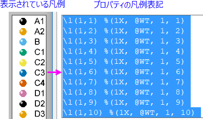
1ポイントずつの凡例で通常使用される「@option」はワークシートのセルへのアクセス用で、具体的には@Vと@WTのオプションを使用します。ワークシートセルへのアクセスをご覧ください。
凡例テキストのカスタマイズ
凡例テキストは ワークシート列に保存されているデータセットのメタデータを組み込んだ%( ) substitution notation によって作成されます。デフォルトでは、グラフテンプレートはワークシートテンプレートとともに保存される 凡例の自動設定を使用します。下記のリストの「@options」を使用してデフォルトの構成を上書きできます。
基本構文
@options変数の使用については上記の個々の凡例タイプの説明を参照してください。
例としてほとんどの2Dと3Dグラフで共通のデータプロットの凡例 を使用します。
%([LayerIndex.]PlotIndex[Axis] [,@option])
- シンボルカラーもしくはサイズがデータセットで定義されている場合、PlotIndex でデータセットの変更を参照する特別な構文に置き換えることができます: カラーマッピング/インデックス作成では?Rを、 サイズインデックス作成では?Sを使用します。
- たとえば、%(1S,@LL)を使用すると最初のプロットのSizeデータセットの列のロングネームが表示されます。
- たとえば、%(1.2R,@LL) を使用すると最初のレイヤの2番目のプロットの色データセットの列のロングネームが表示されます。
- 任意のテキストが混在する複数の「@オプション」を組み合わせるには、次の構文を使用します。
- %(PlotIndex,@(@option1+@option2+...))
- 例えば、 %(1,@(@LL(@LU)))を使用した場合、ロングネームと単位がロングネーム(単位).の形式で結合されます。
- 内側の括弧内には、次のように任意のテキストを混在させることができます。
- %(1X,@(Long Name @LL, Units @LU, Comments @LC))
@Optionsのリスト
以下はグラフの凡例テキストをカスタマイズするためによく使用される @optionsです。すべての@オプションの詳細については、@オプションのリストを参照してください。
Notes:これらの"@"ラベル オプションの多くはワークブック データにのみ適用できますが、一部は行列データにも適用できます。次に例を示します。
%(1,@W) // 行列ブックのショートネームを返す
|
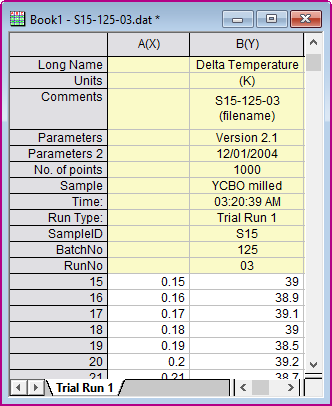
次の表の例は上図を参照しています:
- システムパラメータは常に Parameters, Parameters 2,などの名前が付けられますが、ユーザ定義パラメータにはUserDefined, UserDefined1のような名前やNo. of points, Sample,のような名前も割り当てることができます。
- 構文のプロット部分は番号(「1」など)もしくはプロットデータと同じ列のラベル行セルを参照するワイルドカード「?」を使って参照できます。
| @option
|
置換テキストの参照先
|
例
|
| @D
|
データセット名
|
%(1,@D) --> Book1_B
|
| @GF
|
グラフのフィルタ条件。
ページタイトルには%(Lをサポートしています。例えば%(L[n],@GF)と書いたとき、Lは現在のレイヤ、L2はレイヤ2です。
|
%(1,@GF) --> > 1996
|
| @GFN
|
列名を持つグラフのフィルタ条件。
|
%(1,@GFN) --> Year > 1996
|
| @LA
|
利用可能ならロングネーム、そうでなければショートネーム
|
%(1,@LA) --> Delta Temperature
|
| @LC
|
利用可能ならコメント、そうでなければロングネーム、それもできなければショートネームを参照
|
%(1,@LC) --> S15-125-03 (filename)
|
| @LDn
|
ユーザ定義パラメータのn番目@LD は @LD1 と同じものを指す (2025)n = 0は最後のユーザ定義パラメータです。
|
%(1,@LD2) -->YCBO milled
|
| @LG
|
ロングネーム(使用できなければショートネーム)と単位(あれば)@Uと同等
|
%(1,@LG) -->Delta Temperature (K)
|
| @LHn
|
n番目のユーザ定義パラメータ行の名前@LH1 は @LH と同じ (2025)n = 0は最後のユーザ定義パラメータです。
|
%(1,@LH3) -->Time
|
| @LL
|
列のロングネームロングネームがない場合には欠損値を返します
|
%(1,@LL) --> Delta Temperature
|
| @LM
|
利用可能ならコメントの1行目を、できなければロングネームを、それもできなければショートネームを参照
|
%(1,@LM) --> S15-125-03
|
| @LN
|
コメントの1行目(利用できなければロングネームを、それもできなければショートネーム)を参照@(@LM(@LU)).と同じ
|
%(1,@LN) --> S15-125-03(K)
|
| @LPn
|
n番目のシステムパラメータ。@LP と @LP1 は同じ
|
%(1,@LP2) --> 12/01/2004
|
| @LS
|
列のショートネーム、@Cと同等
|
%(1,@LS) --> B
|
| @LU
|
単位
|
%(1,@LU) --> (K)
|
| @LUP,@LUS,@LUA,@LUC
|
単位に括弧を追加。Pは括弧 = (), Sは角括弧 = [], Aは山括弧 = <>, Cは波括弧 = {}
|
%(1,@LUA) --> <km>
|
| @W
|
ワークブックのショートネーム
Note: @W, UserVar$を使用してユーザ変数にアクセスできます。詳細は後述のインポートしたファイルの情報アクセスセクションを参照してください。
|
%(1,@W) -->Book1
|
| @WCn
|
ワークブックコメントのn番目の行。nの指定がない場合には最初の行のみが表示されます。
|
%(1,@WC2) -->
<Origin EXE Folder>\Samples\Curve Fitting
|
| @WL
|
ワークブックのロングネーム
|
%(1,@WL) -->S15-125-03.dat
|
| @WMn
|
ワークシートコメントのn番目の行。nの指定がない場合には最初の行のみが表示されます。
|
%(1,@WM) -->Data imported from
|
| @WN
|
セルノートの内容。
|
%(1,@WN,1) -->1番目のプロットのソース列の行[1]のノートの内容。
|
| @WS
|
ワークシートの名前
|
%(1,@WS) -->Trial Run 1
|
|
Note: 単位が凡例に表示されている場合、英語と日本語版のOriginでは単位を括弧()で囲みますが、ドイツ語版では角括弧[]を使用します。
|
ワークシートセルへのアクセス
ワークシートセルの内容を返すための特別な@optionsがいくつかあります。@V と @WTオプションは主に1ポイントずつの凡例で使用されます。
| @option
|
置換テキストの参照先
|
例
|
| @L, n
|
データプロット内にあるn番目のポイントのX値
|
- %(1, @L, 2)
- は1つ目のデータプロット内にある2番目のポイントのX値を指します。
|
| @V, n
|
データプロット内にあるn番目のポイントのY値
|
- %(1, @V, 2)
- は1つ目のデータプロット内にある2番目のポイントのY値を指します。
|
| @WT, ColIndex/ColName, RowIndex
|
列番号(もしくはショートネームや行番号)で指定されたワークシートセルの値
|
- %(1, @WT, 2, 3)
- は1つ目のデータプロットのソースワークシートにある2列3行目のセルの値を指します。
- %(1, @WT, B, 3)
- は1つ目のデータプロットのソースワークシートにあるB列3行目のセルの値を指します。
|
| @WT, ColIndex/ColName, ColLabelRowCharacter
|
列番号(もしくはショートネーム)と列ラベルの行の文字で指定されたワークシートセルの値
|
- %(1, @WT, B, C)
- B[C]$と同様に、これは1つ目のデータプロットのソースワークシートにある列Bのコメントを取得します。
|
プロットで使用されていないシンボルの追加
前述のように、凡例エントリはプロットシンボルの要素とテキストで構成されています。通常、凡例プロットシンボルは、グラフウィンドウのデータプロットの1つを使って表示されます。ただし、グラフ内のどのプロットでも使用されていないプロットシンボルを凡例に追加したい場合があります。これが、このセクションでの主題です。
シンボル、線+シンボル、折れ線を構築するためのオプション
Origin 2018以降、凡例オブジェクトのテキストタブコントロール(プロパティ> テキストタブ> 凡例シンボル追加ボタン)を使用して、シンボル(散布図)、線+シンボル、および折れ線グラフで使用されるプロットシンボルを手動で追加できます。
以前は複雑な構文を使用してシンボルを手動で作成する必要がありましたが、これにより、ユーザーインターフェイスダイアログボックスを使用してプロットシンボルを簡単に作成できるようになりました。これを使う場合、シンボルの作成に使用される構文が同時に生成されます。したがって、このユーザーインターフェイスによって、カスタムシンボルを生成するための文字列を簡単に取得できます。
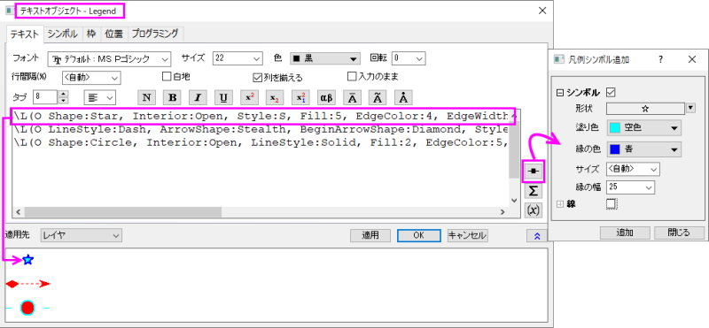
サンプル:
プロパティはコンマ区切りのリストで組み合わせることができます。
\L(O Shape:Star, Interior:Open, Style:s, Fill:3, EdgeColor:4, Size:15.0, EdgeWidth:20.0)
\L(O LineStyle:Dash, ArrowShape:Stealth, BeginArrowShape:Diamond, Style:L, LineColor:2, ArrowWidth:7.0, ArrowLength:10.0,
     BeginArrowWidth:8.0, BeginArrowLength:12.0)
\L(O Shape:Circle, Interior:Open, LineStyle:Solid, Fill:2, EdgeColor:5, Size:14, EdgeWidth:15.0, LineColor:5, Gap:60)
| プロパティ
|
オプション
|
例
|
| Style
|
Style:<keyword> は折れ線およびシンボルシーケンスを設定します(e: s=シンボル, l=線のセグメント)。任意の順序で表示できます。
|
Style:sls
|
| Gap
|
Gap:## はポイントサイズでシンボルとの間隔を設定し、 Gap:p## はデフォルトのパーセントで間隔を設定します( > 100%にできます)。
|
Gap:24
Gap:p200
|
| Size
|
Size:## は散布図シンボルのポイントサイズを設定し、Size:p## は(プロット)シンボルサイズのパーセントを設定します。( > 100%にできます)
|
Size:18
Size:p200
|
| Shape
|
Shape:<keyword> はシンボルの形状を設定します: Square, Circle, UpTri, DownTri, Diamond, Plus, Times, Asterisk, HorizontalBar, VerticalBar, Arrow, LeftTri, RightTri, Hexagon, Star, Pentagon, Sphere
|
Shape:Star
|
| Interior
|
Interior:<keyword> はシンボル内部を設定します: Solid, Open, Dot, Hollow, Cross, XLines, HLine, VLine, HalfUp, HalfRight, HalfDown, HalfLeft
|
Interior:Open
|
| Fill
|
Fill:<index> または Fill:<htmlColor> はシンボルの内部の色を設定します。LabTalkカラーインデックスかHTMLカラーコードで指定できます。
|
Fill:18
Fill:#FFFFFF
|
| EdgeColor
|
EdgeColor:<index> または EdgeColor:<htmlColor> はsolidシンボルの内部の色を設定します。LabTalkカラーインデックスかHTMLカラーコードで指定できます。
|
EdgeColor:1
EdgeColor:#000000
|
| EdgeWidth
|
EdgeWidth:## はポイントサイズでシンボルの縁の太さを設定し、 EdgeWidth:p##はプロットシンボルの縁幅のパーセントで太さを指定します。(>100%にできます)
|
EdgeWidth:15.0
EdgeWidth:p100
|
| LineStyle
|
LineStyle:<keyword> は線のスタイルを設定します: Solid, Dash, Dot, DashDot, DashDotDot, ShortDash, ShortDot, ShortDashDot
|
LineStyle:Solid
|
| LineColor
|
LineColor:<index> または LineColor:<htmlColor> は線の色を指定します。LabTalkカラーインデックスかHTMLカラーコードで指定できます。
|
LineColor:1
LineColor:#000000
|
| LineWidth
|
LineWidth:## はポイントサイズで線の幅を設定し、LineWidth:p## はプロット線サイズのパーセントで線の幅を表示します( > 100%にできます)
|
LineWidth:1.5
LineWidth:p100
|
| Length
|
Length:## はポイントサイズで線分の長さを設定します。 Length:p## は アクティブデータセットの標識の幅のパーセントで設定します。 (> 100%にできます)
|
Length:100
Length:p200
|
| BeginArrowShape
|
BeginArrowShape:<keyword> は矢印の先頭(左側)の形状を設定します: Filled, Empty, Stealth, FilledReverse, EmptyReverse, StealthReverse, Stick, Cross, Diamond, Rectangle, Ellipse, StickUp, StickDown
|
BeginArrowShape:Diamond
|
| BeginArrowWidth
|
BeginArrowWidth:##は 矢印の先頭(左側)のポイントサイズで幅を設定します。
|
BeginArrowWidth:8.0
|
| BeginArrowLength
|
BeginArrowLength:##は矢印の先頭(左側)のポイントサイズで長さを設定します。
|
BeginArrowLength:12.0
|
| ArrowShape
|
ArrowShape:<keyword> は矢印の終端(右側)の形状を設定します: Filled, Empty, Stealth, FilledReverse, EmptyReverse, StealthReverse, Stick, Cross, Diamond, Rectangle, Ellipse, StickUp, StickDown
|
ArrowShape:Diamond
|
| ArrowWidth
|
ArrowWidth:## は 矢印の終端(右側)のポイントサイズで幅を設定します。
|
ArrowWidth:8.0
|
| ArrowLength
|
ArrowLength:## は 矢印の終端(右側)のポイントサイズで長さを設定します。
|
ArrowLength:12.0
|
ブロックを構築するためのオプション
次の表は、ブロックスタイルのプロットシンボルの作成に使用する構文を説明しています。
線、線+シンボル、および線スタイルのプロットシンボルに使用される構とは、いくつかの点で大きな違いがあります。
- \L(O構文は、このスタイルのプロットシンボルではサポートされていません。代わりに、\L(1,構文を使用します。
- \L(1,構文は親データプロットなしでシンボルを作成することができません。\L(O構文では、空のグラフウィンドウの凡例オブジェクトにシンボルを追加できますが、\L(1,構文は、適切なタイプの既存のデータプロット(つまり、縦棒グラフなどの作図の詳細ダイアログのパターンタブを使用するプロット)で開始する必要があります。したがって、凡例に追加するシンボルは、実際には既存のプロットシンボルの修正であり、完全に新しいものではありません。
- \L(O構文はコンマ区切りのリストを使用しますが、 \L(1構文はスペース区切りのリストを使用します。
サンプル:
プロパティはスペース区切りのリストで組み合わせることができます。
\L(1, PatternScale:p200 PatternFill:2 BorderStyle:Dash BorderColor:4 BorderThick:2 Width:40 Height:40)
| プロパティ
|
オプション
|
例
|
| Pattern
|
Pattern:## はインデックス番号でパターンを設定します。1から始まります。
|
Pattern:5
|
| PatternFill
|
PatternFill:## または PatternFill:<htmlColor> はブロックの内部の色を設定します。LabTalkカラーインデックスかHTMLカラーコードで指定できます。
|
PatternFill:#81F7F3
|
| BorderStyle
|
BorderStyle<keyword> は境界線のスタイルを設定します: Solid, Dash, Dot, DashDot, DashDotDot, ShortDash, ShortDot, ShortDashDot
|
BorderStyle:Dash
|
| BorderColor
|
BorderColor:## または BorderColor:<htmlColor> はブロック内部の色を設定します。LabTalkカラーインデックスかHTMLカラーコードで指定できます。
|
BorderColor:#7C9BCF
|
| BorderThick
|
BorderThick:## デフォルトの太さの倍数で縁の太さを設定します。
|
BorderThick:2
|
| PatternWidth または Width
|
PatternWidth:p##または Width:p## はアクティブデータセットの標識のパーセントでブロック幅を設定します。 (最大値 = 100%)
|
PatternWidth:40
|
| PatternHeight または Height
|
Height:p## アクティブデータセットの標識のパーセントでブロックの高さを指定します。 (最大値 = 100%)
|
PatternHeight:20
|
プロットで使用されていないシンボルを追加するための以前の構文(v2017以前)
ある程度の忍耐が必要ですが、プロットされたデータとは関係のない凡例シンボルを作成できます。
次の4種類の構文は、使用するシンボルの種類に応じて、さまざまな場面で使用できます。
| \L(O SymEdgeColor,Sym,Fill,Size,ColorLn,LineStyle,Gap,LnWidth,SymFillColor,EdgeThickness)
|
| \L(S 0, Sym, Fill, SymEdgeColor, SymFillColor, Size, LineStyle, ColorLn, LnWidth, Gap, EdgeThickness)
|
| \L(S 1, SymIndex, SymEdgeColor, Size, , , LineStyle,ColorLn, LnWidth, Gap)
|
| \L(S 1,CharIndex,CharColor,Size,Font,FontStyle,LineStyle,ColorLn, LnWidth, Gap)
|
Note: \L(S )構文を使用する場合、最初の変数を0として定義した場合には、Originの組み込みのシンボルを使用することを意味し、1と定義した場合には、ユーザ定義シンボルもしくはASCII文字を使用することを意味します。
それぞれの変数の定義は下記のリストのようになっています:
| 引数
|
説明
|
| SymEdgeColor
|
Originのカラーインデックス: 1...24(1=黒,2=赤,...)もしくはユーザ定義カラーがあれば24...40から
HTMLのカラーコード: #ff0000 など(the color() 関数を使用する場合はダブルクォーテーションで囲む必要はありません。)から
|
| Sym
|
Originの形状番号を使ってシンボルを指定します。(0 = シンボルなし、1 = 正方形、2 = 丸、3 = 三角、4 = 逆三角、5 = 菱形、6 = 十字(+)、7 = エックス(×)、8 = アスタリスク(*)、9 = 横棒(-)、10 = 縦棒(|)、11 = 数字(1234...)、12 = 大文字(ABCD...)、13 = 小文字(abcd...)、14 = 右矢印(→)、15 = 左三角、16 = 右三角、17 = 六角形、18 = 星、19 = 五角形、20 = 球)
|
| Fill
|
シンボル内側を指定するOriginの番号から選んで塗りつぶします。(0=単色、1=空白、2=中央に点、3=枠のみ、4=+中央、5=×中央、6=-中央、7=|中央、8=上半分塗り、9=右半分塗り、10=下半分塗り、11=左半分塗り)
|
| Size
|
ポイントのシンボルサイズ
|
| ColorLn
|
Originのカラー番号かHTMLのカラーコードで指定します(SymEdgeColor をご覧ください)
|
| LineStyle
|
Originの線種から線種を指定します。(0=実線, 1=破線, 2=点線, 3=1点鎖線, 4=2点鎖線, 5=短い破線, 6=短い点線, 7=短い1点鎖線)
|
| Gap
|
シンボルサイズのパーセントでシンボルと線分の間隔を設定します。
|
| LnWidth
|
ポイントの線分の太さを指定します。
|
| SymFillColor
|
Originのカラー番号かHTMLのカラーコードで指定します(SymEdgeColor をご覧ください)
|
| EdgeThickness
|
0から100までのパーセントでシンボルの枠の太さを指定します。
|
| SymIndex
|
ユーザ定義シンボルにあるユーザ定義のシンボルの順序を指定します。1から31の整数で入力できます。
|
| CharIndex
|
文字のASCIIコードを指定します。32から255の整数で入力できます。
|
| CharColor
|
ASCII文字の色番号を指定します。(SymEdgeColor をご覧ください)
|
| Font
|
フォントリストから特定のフォントのインデックス番号を指定します。インデックス番号を取得したい場合には、スクリプトウィンドウ もしくは コマンドウィンドウで font(fontname)= を実行してください。
|
| Font Style
|
フォントスタイルのインデックス番号を指定します。(下線、イタリック、太字)0=スタイルなし, 1= 下線のみ, 2=イタリックのみ, 3=下線+イタリック, 4=太字のみ, 5=下線+太字, 6=イタリック+太字, 7=下線+イタリック+太字
|
 | 1つの変数を空のままにすると、この変数にはデフォルト値が使用されます。構文 \L(O SymEdgeColor,Sym,Fill,) は Fill のあとのすべての変数にデフォルトの値を使用します。
これらのワークシートセルへのアクセス表記を使ってワークシートセルの値を使用した1つの変数を定義することもできます。
|
線の凡例シンボルを作成する場合、より簡単な構文があります。
\L(L Color, Thickness, Style)
| 引数
|
説明
|
| Color
|
Originのカラーインデックス: 1...24(1=黒,2=赤,...)もしくはユーザ定義カラーがあれば24...40から線の色を指定します。
|
| Thickness
|
ポイントの線分の太さを指定します。
|
| Style
|
Originの線種から線種を指定します。(0=実線, 1=破線, 2=点線, 3=1点鎖線, 4=2点鎖線, 5=短い破線, 6=短い点線, 7=短い1点鎖線)
|
その他凡例のカスタマイズ
凡例テキストの特殊なフォーマット
エスケープシーケンスを使ってテキストフォーマットをカスタマイズできます。よく使用されるいくつかの例を以下に示します:
| 使用構文
|
フォーマットテキスト
|
例
|
| \+(text)
|
上付き文字
|
%(1)\+(2)
|
| \-(text)
|
下付き文字
|
%(1)\-(n)
|
| \g(text)
|
ギリシャ文字
|
\g(m)
|
| \b(text)
|
太字
|
\b(Important)
|
| \i(text)
|
イタリック
|
\i(%(1))
|
| \u(text)
|
下線
|
\u(%(1X,@L))
|
| \sc
|
複数の連続スペースの場合でも、1つの水平スペース
|
\b(%(1Y,@LL)\sc%(1Y,@LD3)\sc%(1Y,@LD4)\sc(%(1Y,@LU)))
|
凡例要素の配置
| Note: 以下の情報によって凡例要素をより柔軟に配置できる場合があります。凡例テキストを右揃えにすることに関心がある場合は、 このFAQを参照してください。
|
凡例シンボルとテキストの配置プロパティを指定するには、グラフをアクティブにして、スクリプトウィンドウで以下のスクリプトを実行する必要があります。
legend.align=1; //turn on the alignment mode
次に、凡例を右クリックして プロパティを選択してダイアログを開き、セルアンカーとして\^()を追加します。これによりアンカー右側にあるオブジェクトの配置が設定されます。\^(l), \^(c), \^(r)はそれぞれ左、中央、右に配置する設定です。次に例を示します:
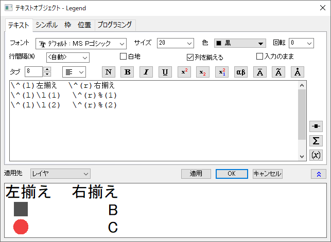
OKをクリックすると、ダイアログのプレビューにあったものと同じ凡例が表示されます。
または、Ctrlキーを押しながらドラッグして、凡例を再配置することもできます:
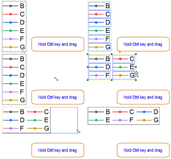
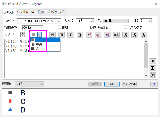
Note: Origin2020b以降には、テキストを簡単に整列できるようにテキストオブジェクト-凡例ダイアログのテキストタブにテキストを整列するドロップダウンリストがあります。
|
たとえば、Ctrl +ドラッグを使用すると、現在の凡例行の右側に凡例オブジェクトを作成できます。この場合、シンボルとテキストの間に\^(l), \^(c), \^(r)の代わりに \^(lu), \^(cc), \^(ru)を使用する必要があります。
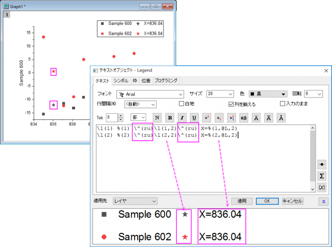
このように、プロットと特別なポイントの凡例アイテムは、以下に示すように、Ctrlキーを押しながらドラッグして再配置すると1つのグループとして扱われます:

それ以外の場合、Ctrlキーを押しながらドラッグして再配置すると、シンボルと対応するテキストが分離されます。

|