2.6.3.4 imgMorph(Pro)
Menu Information
Image: Arithmetic Transform: Morphological Filter
Brief Information
Apply morphological filter to matrix or image
Additional Information
This feature is for OriginPro only.
Command Line Usage
1. imgMorph op:=open emode:=diamond r:=5;
2. imgMorph op:=erosion emode:=rec col:=5 row:=4;
X-Function Execution Options
Please refer to the page for additional option switches when accessing the x-function from script
Variables
Display
Name
|
Variable
Name
|
I/O
and
Type
|
Default
Value
|
Description
|
| Input Image
|
im
|
Input
MatrixObject
|
<active>
|
Specifies the input image, which should be a numeric matrix, a grayscale image or a binary image. The default input is the active image.
|
| Output Image
|
om
|
Output
MatrixObject
|
<new>
|
Specifies the output image. By default, a new image will be created and used as output.
See the syntax here.
|
| Operation
|
op
|
Input
int
|
open
|
Specifies the morphological operation to perform.
Option list
- dilation:Dilation
- Incorporates each object all the background points that are in contact of it, causing the object to grow in size. This operation can be used to removing holes in segmented objects.
- erosion:Erosion
- Decreases the size of the objects by one pixel all around its perimeter. This operation can be used to remove objects that are too small.
- open:Open
- Performs erosion and then dilation on the objects. Small and thin objects can be removed, without significantly changing the areas of the larger objects.
- close:Close
- Performs dilation and then erosion on the objects. Small holes in objects can be filled and nearby objects can be connected. However, the areas of the objects are not affected significantly.
|
| Flat Element
|
flat
|
Input
int
|
1
|
Specifies whether or not to use a flat structuring element.
|
| Height Matrix
|
hm
|
Input
MatrixObject
|
<optional>
|
This variable is available only when Flat Element is set to 0. It specifies the matrix that has the heights of the structuring element.
|
| Create Element
|
emode
|
Input
int
|
rec
|
Specifies the structuring element.
Option list
- arb:Arbitrary
- Uses a matrix object to represent the structuring element. You can specify this matrix object with the Element variable.
- diamond:Diamond
- Creates a diamond-shaped object. You can specify its radius with the Radius variable.
- line:Line
- Creates a line object. You can specify its length and angle with two variables: Length and Angle.
- octagon:Octagon
- Creates an octagonal object. You can specify its radius with the Radius variable.
- pair:Pair
- Creates a structuring element containing a pair of dots. One dot locates in the center; the other one's location is determined by two variables: Row Offset and Column offset.
- pl:Periodicline
- Creates a structuring element that contains 2*p+1 dots, where p is determined by the Points in One Side variable. The relative positions of the dots are determined by another two variables: Row Offset and Column offset.
- rec:Rectangle
- Creates a rectangle object. You can specify its width and height with two variables: Column and Row.
- square:Square
- Creates a square object. You can specify its width with the Width variable.
|
| Element Matrix
|
em
|
Input/Output
MatrixObject
|
<optional>
|
This variable is available only when the Create Element variable is set to Arbitrary. You can use it to specify a matrix object that represents the structuring element.
|
| Column
|
col
|
Input
int
|
3
|
This variable is available only when the Create Element variable is set to Rectangle. It specifies the width of the rectangle.
|
| Row
|
row
|
Input
int
|
3
|
This variable is available only when the Create Element variable is set to Rectangle. It specifies the height of the rectangle.
|
| Width
|
w
|
Input
int
|
3
|
This variable is available only when the Create Element variable is set to Square. It specifies the width of the square.
|
| Radius
|
r
|
Input
int
|
3
|
This variable is available only when the Create Element variable is set to either Diamond or Octagon. It specifies the radius of the structuring object.
|
| Row Offset
|
roffset
|
Input
int
|
0
|
This variable is available only when the Create Element variable is set to either Periodicline or Pair. It specifies the row offset between two adjacent members.
|
| Column Offset
|
coffset
|
Input
int
|
0
|
This variable is available only when the Create Element variable is set to either Periodicline or Pair. It specifies the column offset between two adjacent members.
|
| Length
|
len
|
Input
int
|
5
|
This variable is available only when the Create Element variable is set to line. It specifies the length of the line object.
|
| Angle (in degrees)
|
deg
|
Input
int
|
5
|
This variable is available only when the Create Element variable is set to line. It specifies the angle for the line object. The unit is degree.
|
| Points in One Side
|
np
|
Input
int
|
5
|
This variable is available only when the Create Element variable is set to Periodicline. It specifies a number p. And then, there will be 2*p+1 dots in the structuring element.
|
Description
|
This X-Function is a tool for morphological image processing. It can be used on numeric matrices, grayscale images and binary images.
Generally speaking, morphological image processing is performed by passing a structuring element over the image in a convolution-like operation. The output image is determined by the size and shape of the structuring element, as well as the operation chosen. Morphological Filter is a very important tool widely used in suppressing noise, image segmentation, etc.
A structuring element can be of any shape and any size. It is a matrix consisting of only 0's and 1's, where the 1's defines the neighborhood. Using different shapes of structuring elements is likely to have different effects. And the selection of shape should be determined on a case-by-case basis. The rule of thumb is to choose a shape that is close to the geometric shape of the object of interest. The size of the structuring element is also influential. For example, in erosion operation, if you specify a larger size, only some larger elements in the image are preserved and more small elements are eliminated. If you specify a smaller size, the smaller elements and the details of the image will be more likely to be retained.
Four morphological operations are available in this tool. They are dilation, erosion, open and close. Erosion decreases the size of the objects in the input image, while dilation increases the object sizes. Opening eliminates small and thin objects, leaving the large objects without significant changes in area. Closing fills small holes in objects and smoothes the object boundaries, but it does not change the area of the objects in a significant way. You can choose among these operations according to your need.
|
|
Examples
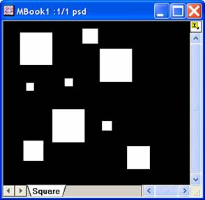
In this example, the input image contains several square objects with different sizes. We use the imgMorph X-Function to remove the small objects from it. The procedure is as follows:
- Create a new matrix and imports the image file into it.
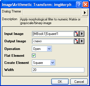
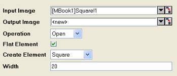
- When the image is active, select Image: Arithmetic Transform: Morphological Filter from the menu to open the dialog of the X-Function.
- In the X-Function dialog, change the settings as the screenshot below and click OK
to close the dialog.
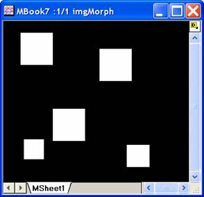
The output image and the structure elements are created. We can see that the output image only has large squares.
|
|
|
Input Image
|
Output Image
|
Structuring Element
Note: OriginPro includes the ability to automatically recalculate the analysis result of the Morphological Filter operation any time you change the parameters or update your source data. In addition, the settings for the analysis routine can be saved to an analysis theme for later use with similar data.
Algorithm
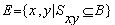
To perform morphological filter on the input image, the structuring element is passed over the image. Let B be the input image and S be the structuring element. We denote by Sxy the translated structuring element whose origin is located at the point (x,y).
The output for erosion can be expressed as follows:
And the output for dilation is:
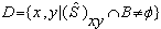
where  is reflection of set S, is defined as is reflection of set S, is defined as
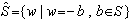 . .
Open operation is carried out by performing erosion once and then dilation once. And closing is carried out by performing dilation once and then erosion once.
References
Kenneth R.Castleman.1996. Digital Image Processing. Prentice Hall, Upper Saddle River, NJ, USA.
Related X-Functions
imgUserfilter
|