2.6.5.3 imgOffset
Menu Information
Offset
Brief Information
Offset image to match a reference image
Additional Information
It is not accessible from script.
X-Function Execution Options
Please refer to the page for additional option switches when accessing the x-function from script
Variables
|
Input Image
|
Specifies the input image. The default is the active image.
|
|
Reference Image
|
Specifies the reference image, which the input image will be aligned to.
|
|
Offset X
|
Specifies the X offset.
|
|
Offset Y
|
Specifies the Y offset.
|
|
Opacity
|
Specifies the opacity of the reference image, when it is displayed in the preview pane.
|
|
Output Image
|
Specifies the output image. By default, a new image will be created and used as output,
|
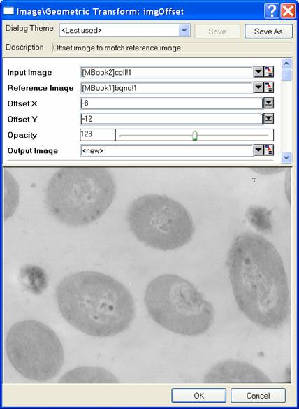
Description
The imgOffset function offsets the input image so as to align it to the reference image.
In the dialog of this X-Function, the reference image can be displayed transparently on top of the input image. You can adjust the opacity of the reference image so that you can see better through it to the input image below. When you change the Offset X or the Offset Y variables, the offset of the input image is updated in the preview pane, allowing you to see the effects and decide whether the offsets are suitable.
Examples
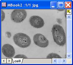
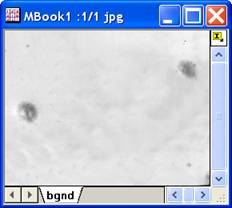
In the following example, we align the cell image to the background image. These two images both have a special "T" mark near its top-right corner. When two images are aligned, these T marks should coincide. The steps to perform the aligning are as follows:
- Create a new matrix and import bgnd.jpg under \Samples\Image Processing and Analysis folder into it.
- Create another new matrix and import Cell.jpg under \Samples\Image Processing and Analysis folder into it.
- From the menu, choose Image: Geometric Transform: Offset to open the dialog of the imgOffset X-Function.
- In the dialog, select matrix that has Cell.jpg for Input Image and the matrix that has bgnd.jpg for Reference Image. In Preview window, you will see both images.
- Click the down arrow at the end of Offset X to see a slider control. Press the Left and Right keys on keyboard to move images in X direction till the "T" marks coincide horizontally in Preview. Do the same thing for the Offset Y.
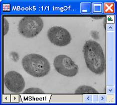
- Click OK to close the dialog.
- A new image is created. It has the offset image.
Input image
Reference image
Offset image
Algorithm
First, the size of the output image is computed according to Offset X, Offset Y and the size of the input image:
-
 , where , where  is the width of the output image and is the width of the output image and  is the width of the input image. is the width of the input image.
-
 , where , where  is the width of the output image and is the width of the output image and  is the width of the input image. is the width of the input image.
Then the input image is copied to the output image with the specified offsets. The copying is implemented with L_COPY_BITMAP_RECT() function from LEADTOOLS Main API. Please refer to the LEADTOOLS Main API Help file, Version 14 and read the L_COPY_BITMAP_RECT topic.
References
LEADTOOLS Main API Help file, Version 14
Related X-Functions
imgCrop
|