PURPOSE
This app can be used to design an IIR comb notch filter, and apply to a signal. It can be used to remove narrow frequency bands near harmonic frequencies and its and keep the rest.
INSTALLATION
Download the file IIR_Comb_Filter.opx, and then drag-and-drop onto the Origin workspace. An icon will appear in the Apps Gallery window.
OPERATION
Make a worksheet for input data active. Click on the IIR Comb Filter icon in the Apps Gallery window. A dialog will open. Dialog settings include:
| Settings |
Description |
| Input Data |
Specify input signal. |
| Design Filter by |
There are two ways to define the design filter:
- Frequency to Remove
Specify the filter by harmonic frequency to remove.
- Filter Parameters
Specify the filter by filter order.
|
| Sampling Interval |
Sampling interval of the signal's x data. |
| Frequency Unit |
Unit for harmonic frequency to remove. Three options are available: Hz, kHz, MHz. |
| Harmonic Frequency to Remove |
Specify the harmonic frequency to remove. It is available when Frequency to Remove is chosen in Define Filter by dropdown list |
| Q Factor |
Quality factor, ratio of harmonic frequency to bandwidth of filter. |
| Order of Filter |
Order of the design filter. The number of notches in the filter is order plus 1. It is available when Filter Parameters is chosen in Define Filter by dropdown list |
| Bandwidth of Filter |
Frequency width where the filter attenuates the response at the specified dB level. It is normalized by half of the sampling frequency, and its range is (0, 1). |
| Magnitude Response at Bandwidth (dB) |
Magnitude response attenuation at the filter bandwidth in dB unit. Default is 3dB. |
| Report Sheet |
Report sheet for the design filter coefficients |
| Result Data Sheet |
Report data sheet for filtered data. |
SAMPLE OPJU FILE
This app provides a sample OPJU file. Right click on the IIR Comb Filter icon in the Apps Gallery window, and choose Show Samples Folder from the short-cut menu. A folder will open. Drag-and-drop the project file CombFilterEx.opju from the folder onto Origin. The Notes window in the project shows detailed steps.
Note: If you wish to save the OPJU after changing, it is recommended that you save to a different folder location (e.g. User Files Folder).
ALGORITHM
For the comb notch filter, the transform function is expressed as:
\(H(z)=\displaystyle \frac{b(1 - z^{-n})}{1 - a z^{-n}}\),
where \(a\) and b are positive parameters, n is the filter order, and the number of notches in the filter is \(n+1\).
The comb filter can be defined by parameters:
- Order of Filter: n
- Bandwidth of Filter: \(w_b\). It is normalized by the maximum frequency \(f_s/2\)( \(f_s\) is the sampling frequency of the signal. ), and its range is (0, 1).
- Magnitude Response at Bandwidth (dB): The level to which the filter attenuates the response at the bandwidth in dB unit. The default value is 3 dB.
The filter can also be determined by Remove Frequency:
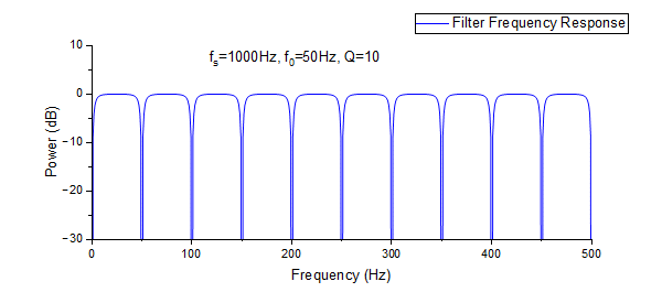
A typical frequency response of the comb filter is shown as below:

REFERENCE
1. Sophocles J. Orfanidis. "Introduction to Signal Processing". Prentice-Hall, 1996.