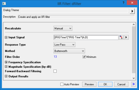
18.3.1 The IIR Filters Dialog Box
IIR-Filter-Dialog
- Menu Command: Analysis: Signal Processing: IIR Filter
- Window Types: Workbook, Graph
- X-Function Script and GUI Examples: dfilter(Pro)
| Recalculate
|
See Recalculating Analysis Results.
|
| Input Signal
|
Specify the input signal. See Specifying Your Input Data.
|
| Response Type
|
- Low Pass: Allow low frequency components to pass.
- High Pass: Allow high frequency components to pass.
- Band Pass: Allow frequency components within a specified range to pass.
- Band Stop: Allow frequency components outside a specified range to pass.
|
| Method
|
Specify the filter design method.
- Butterworth
- Chebyshev Type I
- Chebyshev Type II
- Elliptic
|
| Filter Order
|
If the Minimum check-box is checked, Origin will calculate the order. If unchecked, specify an integer value as the filter order.
|
| Frequency Specification
|
Specify the frequency specification for designing the IIR filter.
- Unit
- Hz: Use Hz as the unit when specifying the frequency specification.
- Normalize to (0, 1): Frequency is normalized to the region from 0 to 1. It is calculated by Frequency(Hz)/(SampleFrequency(Hz)/2), where SampleFrequency(Hz)/2 is the Nyquist frequency.
- Sample Frequency: Specify the sample frequency of the signal (Unit is Hz). By default, Origin will detect the sample frequency according to the associated X column (if such column exists).
- Pass, Stop and Cutoff Frequencies. Varies by Response Type, Method and Unit.
|
| Magnitude Specification (by dB)
|
Specify the magnitude specification, the unit will be dB.
- Pass Ripple: Specify the pass band ripples in dB.
- Stop Attenuation: Specify the stop band attenuation in dB.
|
| Forward-Backward Filtering
|
Perform both forward and backward filtering on the input signal.
|
| Output Results
|
Specify the output results, including designed filter and the filtered signal. See Output Results.
- SOS Matrix: Output the SOS (Second Order Section) matrix of the designed filter.
- Zeros Poles and Gain: Output the zero-pole-gain of the designed filter.
- State-Space Form: Output the state-space form of the designed filter.
- Coefficients: Output the coefficients of the transfer function of the designed filter.
- Output Signal: The output signal after filtering by the designed IIR filter.
|
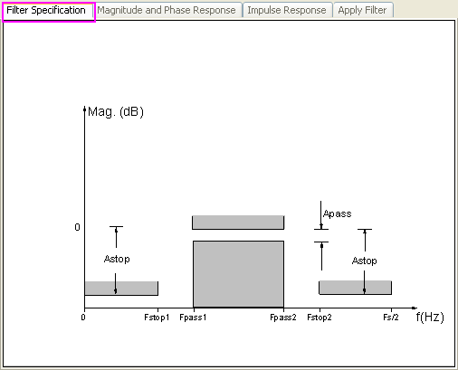
Preview Panels
Filter Specification
When change the Response Type, Method, Filter Order, or Unit, this preview will be changed accordingly, so to make it easy to see the filter specification for designing the IIR filter.
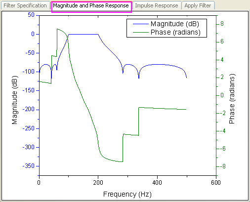
Magnitude and Phase Response
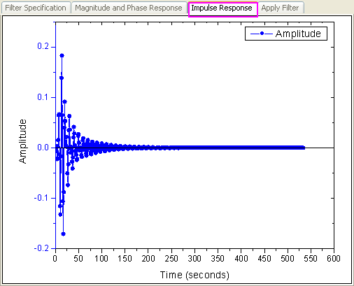
Impulse Response
Apply Filter
This preview tab shows the results after using the designed IIR filter on the original signal. The upper plot shows the original signal and the filtered signal. And the lower plot shows the frequency distribution. It also allows to specify the filtering frequency manually in the lower plot by dragging the vertical lines.
